I have received numerous emails about the FEI 5650A Option 58 oscillator. Here is a collection of useful information.
|
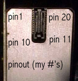
Fixing up the FEI 5650A Option 58 b package Congratulations- You've got a Rb clocked frequency synthesizer! (With very few modifications) Basically, this clock seems to have been designed to produce a 1-sec pulse similar to the one from a GPS running in timing mode. First, look at the accompanying connector image. The pinouts are:
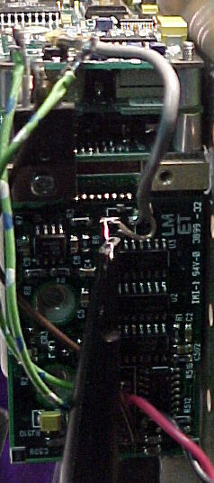
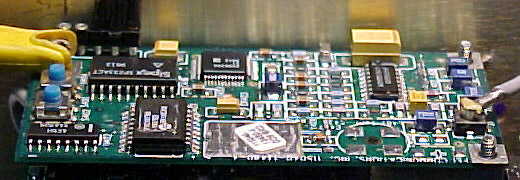
The connector is apparently an Amphenol type 140655-3 or 140656-2 Digi-key A3107-ND or A3111-ND, not sure which at this point. Com is case ground and the common negative for the +15 and +5 volt supplies. The unit will run at +15 although that leaves about 1 volt drop across the regulators. It will run at +15 with no heatsink on the regulators. Higher input requires the heatsink on the regulators. Current drain is over 1.5 amp on warmup, 700 ma after warmup. Warmup about 5 min. +5 v drain about 200 ma or less. Take off the cover. The Al block also needs to be removed. Take the power board off the al block, which is part of the heatsink for the voltage regulators (there are two of them). Pin 18 may be a standby or something. The device works just fine with this pin floating. Now that the power board is exposed, solder a stub on the coax board point; that's where the frequency output is. It's a sine wave, probably will not drive very much. Just to the left of this point is a comparator that will give a pulse out at the freq of the output. Also on the power board is a binary countdown that is not too interesting. If you have fired up the system by now, you'll find a frequency of 8.38860 MHz, which, when divided by 2^23 gives a 1 sec pulse on pin 14. To begin the fun, get a 9-pin or 25-pin com port cable and either cut one connector off (get the right one!) or else get a 9-pin or 25 pin solder pot connector. On the freq divider board and picture, look at the upper left corner, see a row of 5 pins. From the RIGHT as you look at them, the pins are gnd(com), rs232 Transmit (from the device perspective), rs232 receive, +5, and +5. Hook up the connector to a com port. If it's a 9 pin, pin 5 to gnd, pin 2 to the transmit, and pin 3 to the rcv pin. Connect 6 and 7 together on the solder connector or connect the wires together to fool the PC com port. If you have a 25 pin connector or cable, put pin 2 to rcv, pin 3 to xmit and pin 7 to ground. Connect pins or wires on pins 4 and 6 together. Fire up your hyperterm or other communications program, set it to the appropriate com port, 9600 baud, 8 bits, one stop, no parity, no control, Fire everything up, and type a capital S to the device. It should respond with If you don't get this exact number, don't panic, but they should be close. You may have to put a lf after cr on the terminal program or some such. Also set the terminal to echo what you type, because the device does not echo what is typed to it. Now go to the Analog Devices website, and download the data sheet (PDF) for the AD9830A. Look on the data sheet, and see how it works, check the arithmetic between the F= first 8 hex characters and the reference frequency R=, keep pounding. To change the output frequency, simply type F=(8 hex digits that you have calculated) cr and you will see the frequency change at the jury-rigged test point! Typing R= followed by the reference frequency will set the reference frequency. Verified by typing S cr. If nothing further is done, the system will return to the original F and R values on a power cycle. To fix the new values into the microprocessor, type E cr (presumably for enter). The little buttons (two) on the divider board increment and decrement the hex divisor by one lsb per press. S402, furthest from the rs232 pins increments, and the other, s401 decrements. These decrements or increments stay fixed on power cycle. Note that if you want to increment or decrement as a disciplining possibility, simply carefully stick some leads on the switch leads, the switches pull to ground on closing! So, a simple phase comparator with an external source could be used to discipline the divider. Also, on the divider picture, see a test point near the center at the top. This is where you measure the reference frequency of about 50.0225 MHz. I think maybe the frequency was measured here at the factory, entered in to the PIC and that's what comes back as R=. Then the appropriate divisor was set into the 9830 using the F= command, so the appropriate output frequency could be set without having to wait a very long time to measure output against some other standard. These numbers were set using the E cr command. Selah |
|
Hello Tom,
Below is a JPEG of an autocad drawing that I made detailing the FE5650A option-58 pinout. If you have any problems with printing it let me know. If necessary I can send you an autocad printing via snail mail. By the way I have 2 of the connectors being sampled to me from the AMP company. Found a sympathetic parts tech. Next problem will be to find the right size ribbon cable for that small connector. There are 2 switches on the board that you can view without disassembly. Be careful pushing those buttons with power applied !!!!!! I was told that they are used to set the on frequency adjustment for the Rubidium physics package and are not useful in changing the output. The center frequency of the Rubidium physics package is never the same between any 2 packages, or so I was told !! Sounds plausible at any rate. There are factors that affect the final outcome of the physics package. Such things as level of the 6 GHz signal into the cavity, the final temperature of the package, etc.. I was told that the value of adjustment was set so that there was an expected 10 year life for the range of variables. This suggests that there is an overall loop that is under control the cpu. However, the guy that I was talking with that gave me the pinout data was not interested on giving me too much further information in any concrete terms. As I was playing dumb for the most part, I did not press the matter. The pinout info was the most important data for the time being. Keep me advised on your progress and I will do the same. 73's....Bill....WB6BNQ |
LeapSecond.com home
page.
Send comments/questions to tvb.