Trimble Palisade GPS 1 PPS time source
Much less expensive than a rack mount GPS receiver and much easier to use
than an OEM GPS receiver board, the Trimble Palisade is a self-contained antenna
and receiver built into one weather-proof plastic housing.
On board power regulation.
Interface signals are RS-422 not RF not coax not RS-232
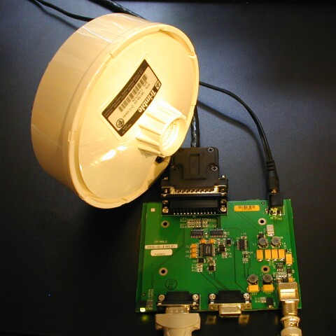 |
| Trimble Palisade antenna/receiver module
shown with SIM board |
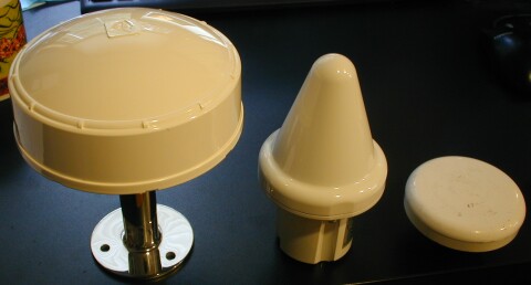 |
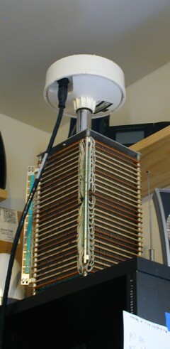
| Palisade size comparison with HP 58532A and
HP 58504 antennas |
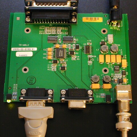 |
| SIM interface board: serial port B, serial
port A, 1 PPS BNC |
1 PPS Output waveforms
The Trimble Palisade is a self-contained GPS antenna and receiver which
generates a UTC synchronized 1 PPS output, automatically performing cold-start
and auto-survey as necessary. Two RS-422 serial interfaces and one RS-422 1 PPS
interface are provided. An optional SIM (Synchronization Interface Module) is
available which converts the RS-422 serial lines to DB9 RS-232 and the RS-422 1
PPS to a TTL pulse on a BNC connector.
 |
| fast rise time, 3 V, rising edge 1 PPS output |
The Palisade antenna/receiver module produces a RS-422 differential 1 PPS output
on Palisade connector pins 11 and 12 which become DB25 pins 9 and 21.
 |
| RS-422 DB25 pin 9 (1 PPS transmit minus) |
 |
| RS-422 DB25 pin 21 (1 PPS transmit plus) |
 |
| Pins 9 and 21 |
 |
| By contrast here's a view of serial IO pins |
How to use the Palisade
MMP refers to the concentric connector on the bottom of the Palisade.
- Apply 24 VDC (actually 9 to 32 is fine) to MMP pin 1 (red)
- Ground is MMP pin 9 (black)
- Ignore RS-422 Port A lines (violet, orange, brown, yellow)
- Ignore RS-422 Port B lines (white, gray, green, blue)
- 1 PPS output plus is pin 11 (orange/white)
- 1 PPS output minus is pin 12 (black/white)
Startup procedure
- Apply power
- Wait about an hour for unit to acquire satellites and perform site survey
- 1 PPS will start working at this point
Do not ground either 1 PPS output. It is safe to use one side of the 1 PPS
(e.g., pin 11) as your 1 PPS signal using ground as a reference. You will then
get a 1 VDC to 5 VDC rising edge lasting 1 us each second.
You can use the PC program PalisadeMonitor.exe to monitor the GPS receiver.
For this you need to convert the port B signals to RS-232. This can be done with
commodity converters or the special Trimble SIM box.
The antenna should be mounted on a roof with a decent view of the sky. But for
quick testing placing the antenna near the ceiling of my upstairs lab works
pretty well.
 |
| indoor ceiling antenna location |
Some views of RS-422 1 PPS output
Black/white to outer shell of BNC (ground). Orange/white to inner pin
(signal)
 |
| RS-422 1 PPS raw output (approx 12 Vpp) |
 |
| RS-422 1 PPS w/ 50R term (approx 5 Vpp) |
 |
| RS-422 1 PPS to 50R to DC-block (0-5V) |
 |
| RS-422 1 PPS to DC-block to 50R (messy) |
![]() |
| what |
![]() |
| what |
![]() |
| what |
![]() |
| what |
![]() |
| what |