30-Aug-2007
| Voltage | Current (Trimble spec) | Actual (during warm-up) | Actual (in operation) |
| +12 V | 750 mA | 530 mA | 160 mA |
| +5 V | 400 mA | 260 mA | 260 mA |
| -12 V | 10 mA | 3 mA | 3 mA |
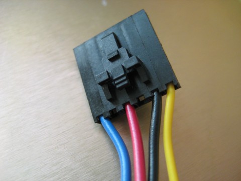
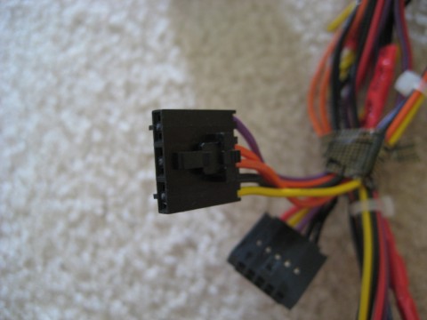
The Thunderbolt uses a 6-pin Molex SL power connector. Only 4 power wires are needed (+12V, +5V, -12V, and ground). Two pairs of pins are redundant at the PCB level. Since currents are relatively low on this GPSDO, even during warm-up, I don't bother with wires to all six pins.
These connectors are available from Mouser Electronics. The 6-pin plastic shell housing is part number 538-50-57-9406 and gold plated female contact crimp pins are part number 538-16-02-0103. Cost per assembled connector is a little over $1.
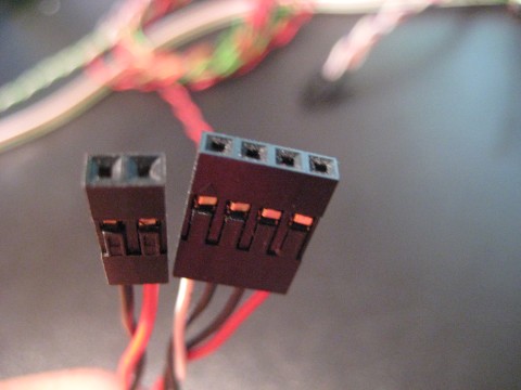
In the connector shown below (consistent with PC power supply wiring conventions), red is used for +5V, yellow for +12V, blue for -12V, and black for ground.
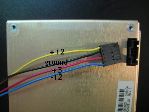
Molex pin 1 is +12V, ground is pins 2 or 5, Pins 3 and 4 are +5V, and pin 6 is -12V. There appears to be no need to connect both ground pins or both 5V pins.
A workable but less elegant connector solution includes using surplus PC motherboard connectors (since they are also 0.1 inch). Note these are neither 6-pin nor keyed so care should be taken in their use:
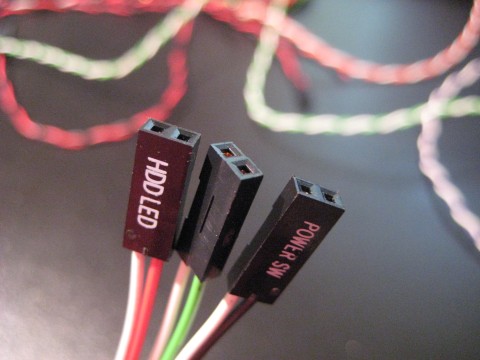
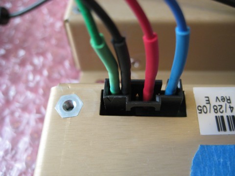
Square pin header jumper wires can also be used as in the following photo (+12=green, 0=black, +5=red, -12=blue):
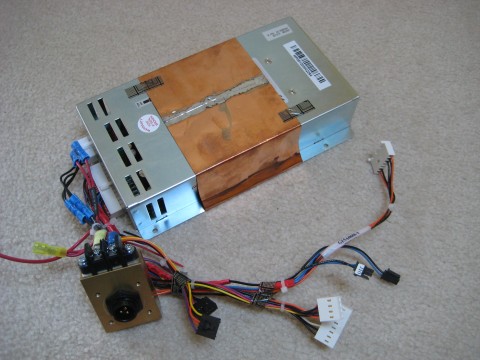
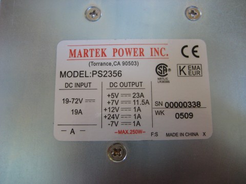
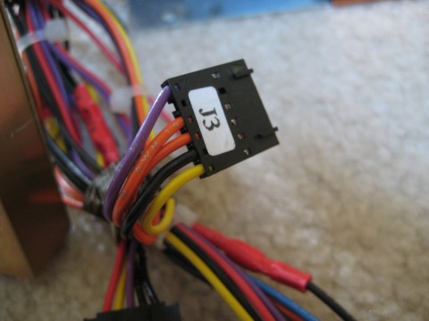
Some versions of this surplus Thunderbolt come with a massive -48V DC-DC cabinet power supply. This is inconveniently large and heavy for the little Tunderbolt but if you have one (along with the required 48 VDC input) the Thunderbolt uses the J3 connector as shown below (purple=+12V, orange=+5V, black=0, yellow=-12V).
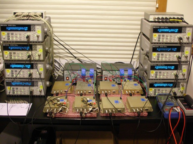
Eight Thunderbolt's being tested at a time using a pair of triple DC power supplies.