PIC divider jitter measurement
Setup
Use two TAPR/T2-mini boards with common low noise 20 MHz reference (Wenzel ULN).
Use divide-by-24 PIC divider so output is 833 kHz.
Measure performance of the two independent outputs as DUT and REF using TimePod 5330A.
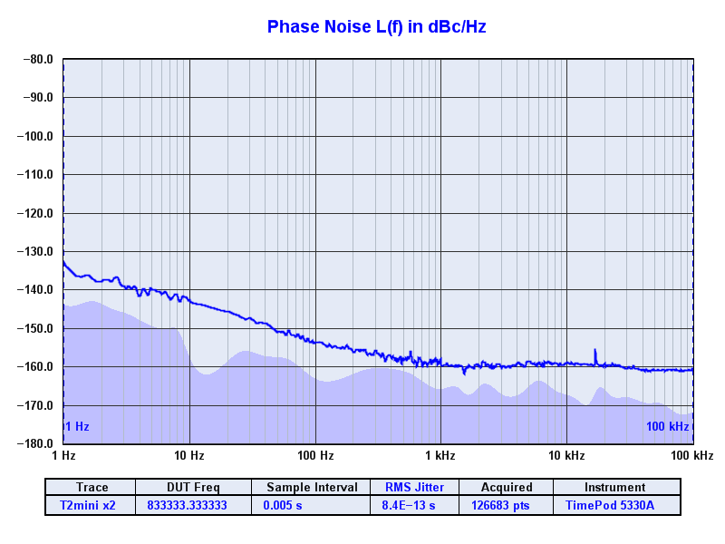
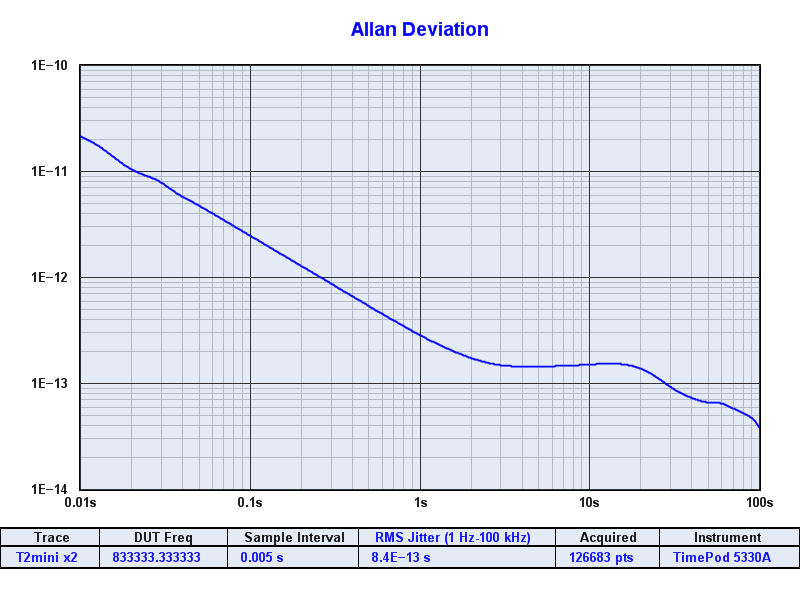
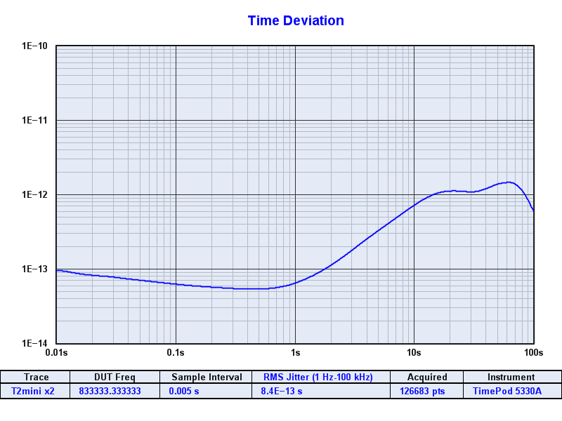
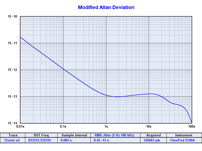
Look at PN and ADEV/MDEV/TDEV/MTIE.
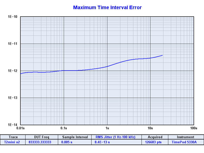
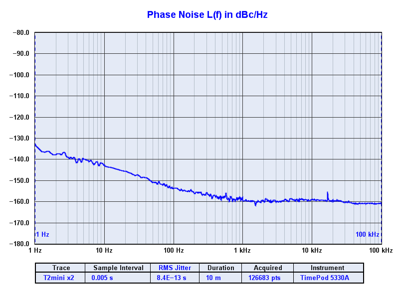
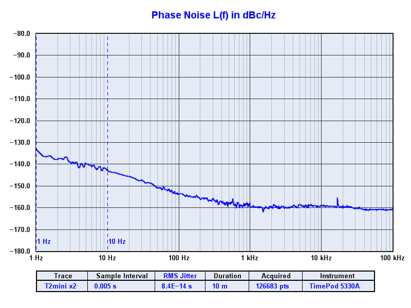
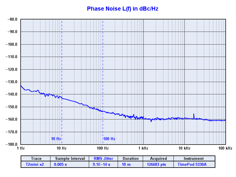
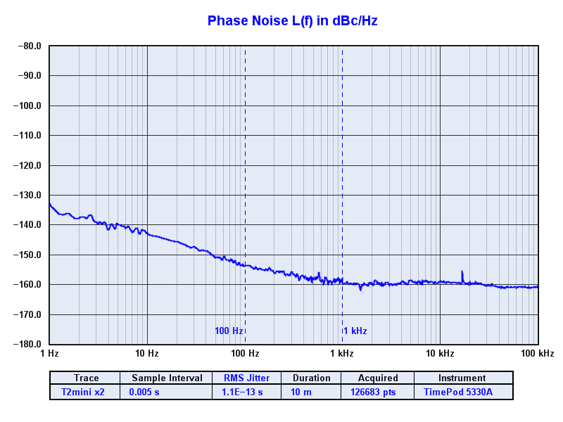
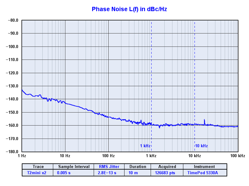
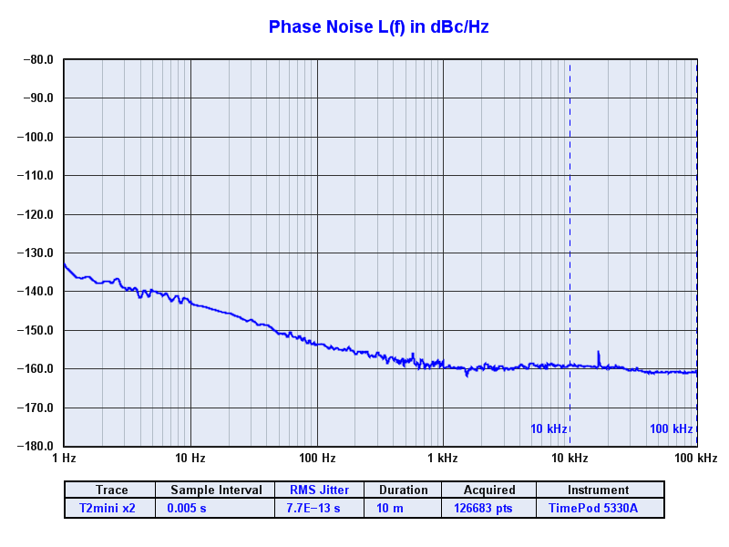
Select integrated "RMS Time Jitter", from 1 Hz to 100 kHz.
Note that jitter of single T2-mini + picDIV is sqrt(2) of measured results.
The PIC code for minimum divider is two line loop.
That's 3 instruction cycles,
which is 12 clock cycles per toggle,
which results in a divide by 24 square wave.
        movlw   0xFF
loop:   xorwf   GPIO,F
        goto    loop
Results indicate the jitter of a T2-mini and its 8-pin PIC 12F675 PIC divider is under 1 ps.
Plots
Baseline (instrumentation noise floor)

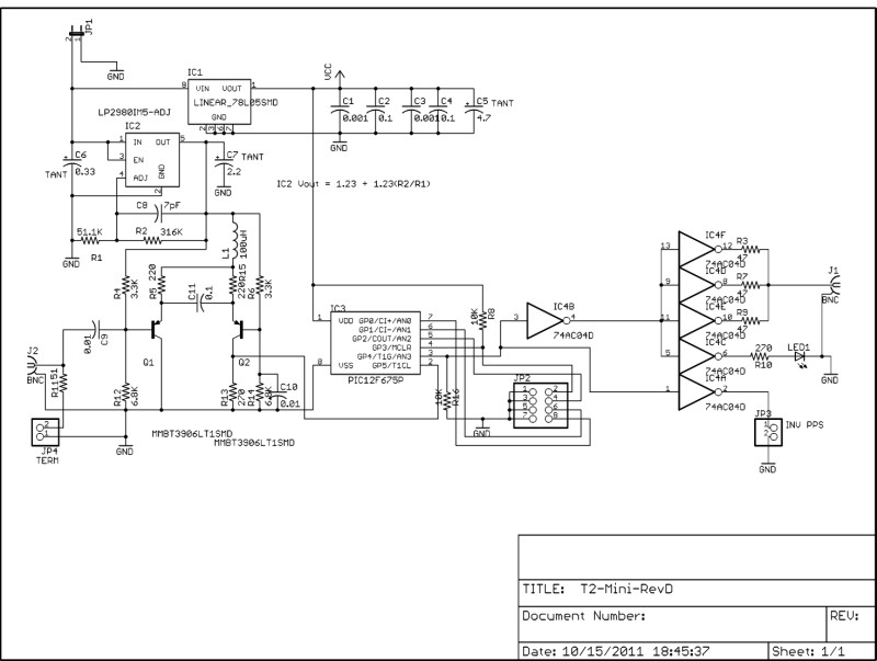
T2-mini schematic
TimeLab integrated jitter calculation, per decade
Send quetions/comments to tvb